|
Master Watchmaking
A Modern, Complete, Practical Course
Lesson 22
PRINCIPLES OF THE LEVER ESCAPEMENT
Chicago School of Watchmaking
Founded 1908 by Thomas B. Sweazy
HOW THE ESCAPEMENT WORKS
The escapement has three main parts: The escape wheel, the pallet assembly, and the rollers. Power from the mainspring turns the escape wheel clockwise while the rotation of the balance Wheel turns the rollers, which are on the balance staff.
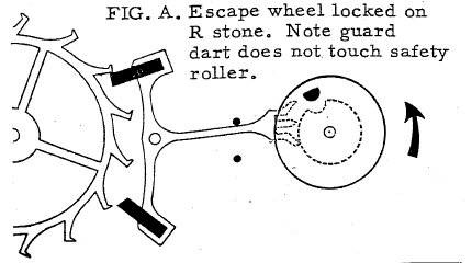
In Fig. A, the escape wheel is locked on the receiving stone. Nothing is moving except the balance, which is turning counter-clock wise, as indicated by the arrow. (The balance and hairspring are not shown because they would block the View of the fork and roller action.) The roller jewel is approaching the fork.
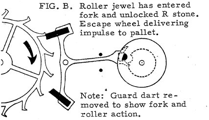
In Fig. B, the roller jewel has entered the fork slot and struck its far side, putting the fork lever into motion. This pulls up one arm of the pallet and also causes the escape Wheel to back up slightly or recoil. The pallet stone slides on the corner of the escape wheel tooth until the corner of the tooth passes the corner of the escape wheel. This releases the escape wheel.
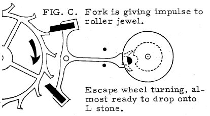
Power from the mainspring now drives the freed escape wheel clockwise. As it turns, the tooth of the escape wheel slides on the impulse face of the pallet stone and kicks it up out of the way, driving the pallet arm higher, Fig. C. This speeds the movement of the fork compared to the speed of the roller jewel. The fork strikes the jewel from behind and gives it a shove. This gives the impulse to the balance which continues to turn, causing the hairspring to contract or wind up.
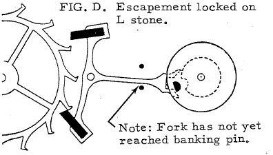
As the escape wheel tooth slides off the impulse face of the pallet stone, the wheel turns freely for a short distance. This phase is known as the drop. When the impulse forces up the receiving arm of the pallet, it also forces the discharging arm of the pallet to move down and halt another tooth on the discharging stone. This phase is called lock, Fig. D.
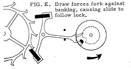
After halting the tooth, a force called draw causes the stone to move further into the wheel. This movement after the lock is called slide, Fig E.
With the escape wheel locked, the roller jewel , carried by the balance, swings free of the fork slot and continues to move counter-clockwise until it is stopped by the contracting hairspring. At this point it reverses direction and the same sequence begins again going the other way.
|
|
SEC. 404 -- Unequal Roller Shake
The, guard pin should be perfectly central with the fork slot under all conditions. It should never tilt from the perpendicular in a single roller escapement. In a double roller escapement, a line drawn from the point of the dart to the center of the pallet arbor should pass through the center of the fork slot and be parallel with its sides.
|
|
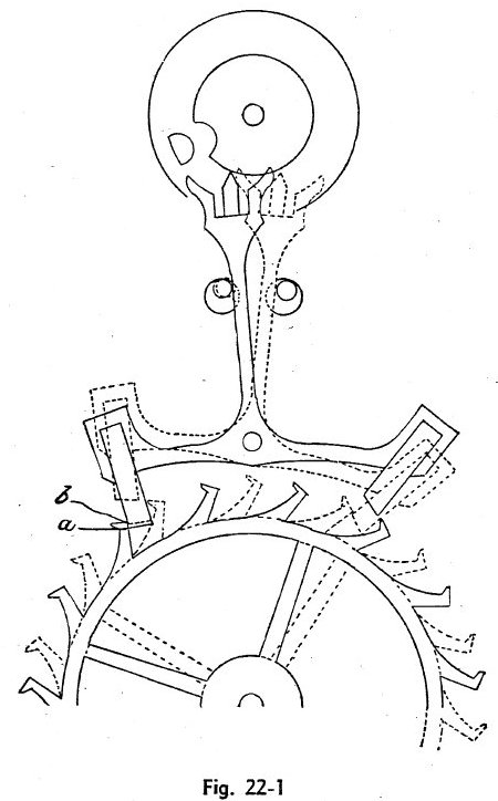
Figure 22-1 shows an escapement with unequal roller shake. The full lines show an escape tooth looked by the receiving stone, the pin touching the left edge of the safety roller. When the lock takes place on this escapement the locking corner of the tooth strikes the face of the stone at the position shown by the broken line parallel with it, but in order that the dart should free the safety roller, the left banking pin was opened from the position shown as dotted line to that shown as a full line. This allowed the pallet stone to slide down on the tooth until the locking corner of the tooth was at point b, and the locking corner of the stone at point a. Now inasmuch as the banking pin must be moved even more in order to give sufficient freedom to the safety roller, the distance that the stone projects below the locking corner of the tooth will be further increased to the detriment of the escapement, and entailing a loss of power.
The fork shown in broken lines in the same figure is in the position in which a tooth is released by the receiving stone and is properly locked on the discharging. Examining the position of the dart with reference to the safety roller we find that it is at some distance from its edge. This is the condition technically called Out of Angle. There are several impractical means resorted to for its remedy. One is to bend the guard pin as shown in figure 22-2. This, however, throws it out of line with the center of the fork and should therefore not be tolerated. Another method is to draw out the discharging stone and push in the receiving stone a sufficient amount to correct the out of angle; but moving a pallet stone in or out produces several changes in an escapement and it should never be done without previously thoroughly examining the escape wheel and pallet action so as to avoid the danger of creating another error.
Figure 22-2 shows the effect of bending the guard pin out of line with the center of the fork slot. In this drawing the guard pin is bent to the left to correct the defect in the safety action shown in figure 22-1. This alteration leaves the escapement with correct lock and slide. The safety action is correct so far as guard pin and roller are concerned, but the impulses, delivered by the pallets to the roller jewel, are at unequal distances from the line of centers. The greatest portion of the impulse on the receiving stone is delivered after the line of centers has been passed; the least amount on the discharging stone. A condition of this character would seriously affect msochronmsm and position adjustment. A more serious error has also been created. Referring to figure 22-2 it will be seen that corner A of the fork slot will not permit the impulse pin to pass freely out of it, while at the other side at the point marked B, there is more room than is required. This might be remedied by grinding way the left horn of the fork, but it would still leave the unequal pulse.
The condition just described, however, is not the most serious one resulting from bending the guard pin to the roller shake. The escapement is liable to do what is technically called trip. The escapement shown in figure 22-2 would do this. If the fork should be pressed to the left when the escape tooth is locked on the discharging stone and the point of the guard pin is opposite the passing hollow, the tooth might unlock from the discharging stone.
|
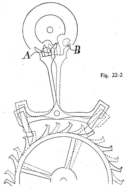
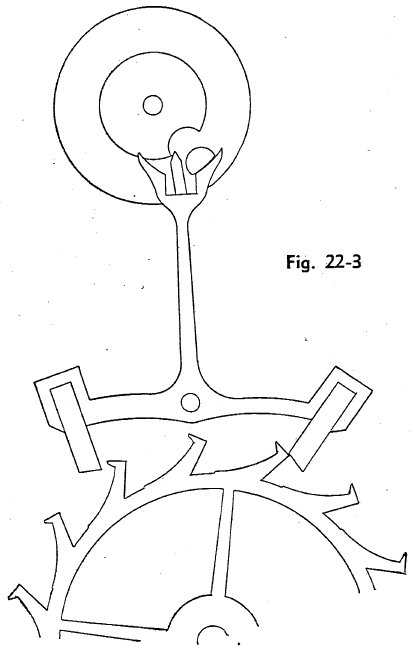
Figure 22-3 illustrates the above. In this figure an escapement is shown with the guard pin bent as in figure 22-2. The roller is assumed to have moved from the position there shown to the position shown in figure 22-3, or until the passing hollow is opposite the guard pin. In this position the fork has been pressed to the left. The safety action between the roller jewel and fork horn fails to arrest the movement of the fork until the escapement has unlocked on the discharging stone as shown.
Moving the pallet stones for the sole purpose of changing the roller shake is a method often practiced, but it is not to be advised. It necessitates more time and jeopardizes the escapment action. A pallet stone can not be moved without altering the escapement in at least four particulars: Impulse, draft, lock and drop.
The simplest and best method of making the alteration is to bend the fork. This alters no other functions of the escapement.
Bending a fork is an operation of which many students stand in awe, but there is little danger if done carefully.
|
|
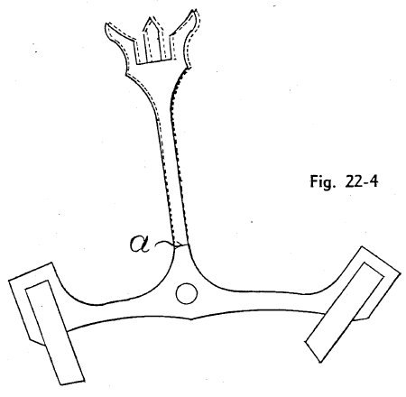
Before attempting to bend a fork ascertain whether it is of sufficiently low temper to permit doing so with safety. It is not necessary to disfigure a piece made of steel in order to ascertain whether it is hard or soft. Use a fine, sharp file. Place it on an unpolished part of the piece to be tried. Without actually moving the file,exercise a gentle forward pressure. If the steel is hard it will offer no resistance to the movement of the file. If it is not hard the file will cling to the steel, more or less, in proportion to the temper. A little practice will enable anyone to become expert at this method. It is seldom that a fork is too hard to permit bending, but should it be, there remains but one of two courses to pursue: Let it alone or take the stones out and draw the temper. There is no objection to reducing the temper of a fork to a sufficient amount to allow it to be bent with safety. Figure 22-4 shows where the bend should be made. If it is done at point a, a very little bending will be sufficient.
There are several methods practiced in bending a fork. It may be set edgewise on a soft metal block and struck lightly with a punch. It may be bent between dies or jaws of pliers especially shaped for the purpose. Or it may be peened with a hammer.
To summarize the conditions necessary for correct safety action: The guard pin central with the fork slot; the sides of the fork slot parallel and of equal length; the inside curves of the fork horn of the proper arc and equal in relation to the fork slot; the roller jewel squared in front and upright; the edge of the safety roller perfectly polished and free from imperfection; the escapement in angle.
SEC. 405 -- Guard Pin Too Far Forward
When the guard pin is too far forward the banking pins are sometimes opened to allow the roller to pass. This method should never be resorted to for the reason that it increases the slide as well as the angle of contact between the roller jewel and fork, both of which incur a loss of power,
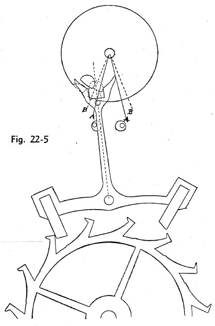
Figure 22-5 illustrates this condition in a single roller escapement. The single roller is used for the reason that it is desired to show how that form of escapement can be corrected for errors caused by the incorrect distance of the guard pin from the pallet center.
It will be observed that, in order to clear the guard pin from the roller edge, the banking pins have been opened, thus making the slide excessive as indicated by the position of the receiving stone with relation to the tooth which it locks. This imposes additional work upon the balance in unlocking the escapement. It also, as has already been pointed out, increases the angular distance during which the roller jewel and fork remain in contact. The full lines, AA, indicate the angle of contact as it should be; the broken lines, BB, indicate the angle of contact with the banking pin open to allow the guard pin to clear the roller edge.
The angle of impulse of a roller is where the two radii from the roller center through the roller jewel center intersect lines running from the pallet arbor through the center of the fork slot. In figure 22-5 this angle is shown in broken lines. It will be noticed that the lock in this figure is excessive. If reduced to the proper amount the impulse angle would be as represented by the full lines AA.
Experience has taught us that a short arc of impulse produces better results than a long one.
|
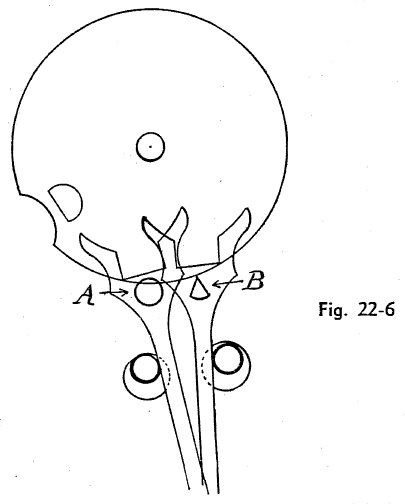
To remedy a guard pin in a single roller escapement which is too far forward, proceed as follows: Push the guard pin through a small piece of tissue paper, the object being to prevent marring the polished face of the fork. With a fine file, dress the pin to a point as shown at B, figure 22-6. A is the pin before being dressed down. It may be reduced as much as necessary without injury to the safety action. In fact, a V-shaped safety pin is superior to a cylindrical one in this particular.
In the double roller escapement an alteration in the length of the guard pin is so simple that instruction is deemed unnecessary.
SEC. 406 -- Guard Pin Too Far Back
|
A guard pin which is too far back in a single roller can be corrected by simply driving the guard pin out, breaching out the hole in the fork and inserting a larger pin.
The guard pin in figure 21-27 is rather short. It is short the same amount as the guard pin in figure 21-26 is too far back. As has been previously explained, the fork in figure 21-26 would go out of action, but while that in figure 21-27 not, its action would be improved by stretching the dart.
|
|
SEC. 407 -- The Escape and Pallet Action
The escape and pallet action is the most intricate function of the escapement. A thorough knowledge of it calls for thoughtful study. Yet there is nothing about it that can not be mastered by the student. In treating it, it is deemed best to divide it into five branches: Impulse, Draft, Lock, Slide, Drop.
SEC. 408 -- Impulse
An escape tooth, in delivering impulse to a pallet, moves in an arc of 12 degrees.
In the ratchet tooth escapement all the pulse is on the pallet; otherwise the same rules apply to it as to the club tooth. A brief description of the ratchet tooth escapement will be given later on.
The chief advantage of the club tooth escapement over the ratchet tooth is that the former can be constructed with less loss of power from drop. A minor advantage is that there is less liability of wedging the guard pin against the roller edge when the train is reversed, which sometimes occurs in setting the hands backward.
In the club tooth escapement, the circular impulse is divided between the tooth and the pallet stone. This division is in various proportion, usually the narrow limits of four--tenths to the tooth and six-tenths to the stone, and equal amounts to both.
|
|
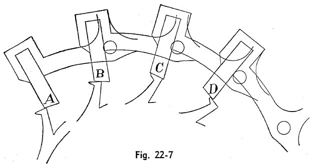
Figure 22-7 illustrates a good type of action. In this drawing an escape tooth is shown in four positions while delivering impulse to the receiving stone. It will be observed that when the tooth begins to pass over the stone, as at A, the impulse faces diverge from each other. In this position only the locking corner contacts the impulse face of the stone, and from this point the faces diverge backwards to the locking corner of the stone. At B the tooth is shown having passed further along on the impulse face of the stone and a divergence at a somewhat less angle is seen. As the lmpulse progresses the faces of the tooth and stone coincide in the position shown at C. From that point the divergence begins to appear in the reverse direction as at D, and continues tooth is released. This is called a natural divergence. It is less apt to cause wear and also reduces friction.
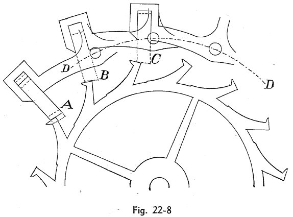
As previously stated, an alteration made in an escapernent by movmg a stone in or out changes the impulse action. Figure 22-8 shows the effect of changing the position of a receiving stone. In order to demonstrate the actual result of moving a stone, the pallets are drawn in three positions in relation to the Wheel. At A, the stone is shown in correct position in full lines. It is shown in dotted lines drawn out. It is shown in broken lines pushed in. The back as well as the impulse face of the stone is indicated by similar lines. The centers of the three pallets are equi-distant from the center of the escape wheel, as indicated by the line DD. The position at A is normal; that at B is with the stone drawn out to the dotted line; that at C is with the stone pressed in to the broken line.
It will be seen that moving the stone outward as at B increases the divergence backwards from the locking corner of the Wheel; that moving the stone inward, as at C produces a divergence in the opposite direction. The latter is considered a bad action for the reason that the locking corner of the stone scrapes across the impulse face of the tooth, wearing it away rapidly.
Moving a discharging stone produces results directly opposmte to those resulting from moving the receiving stone.
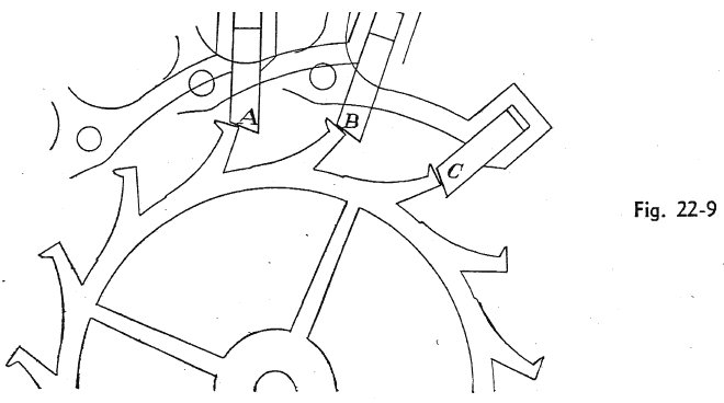
Figure 22-9 shows the effect on the impulse of moving a discharging stone. At C, where the stone is pushed in, the divergence is excessive; at B, where the stone is drawn outward, the divergence is in the wrong direction; at A, where it is in proper position, the divergence natural.
There is another result from moving a pallet stone which must not be overlooked. It changes the extent of the arc of vibration of the pallets. In other words- it changes the lift.
The term lift is applied to the thrust given to the pallets by an escape tooth. In the lift the pallets, swing on their own center and the extent of that swing is called the arc of vibration. It has been explained that the circular impulse is measured from the center of the escape wheel and is divided between an escape tooth and a pallet stone. The lift is measured from the pallet stone and is also divided between an escape tooth and a pallet stone.
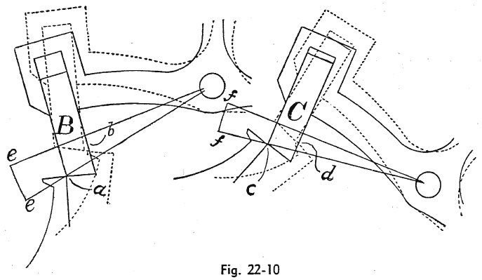
Figure 22-10 shows variation in lift caused by changing the position of a receiving stone.
The positions of the stones B and C are identical with those similarly marked in figure 22-8. That is, they are located in the same position at B, figure 22-10, as at B, figure 22-8; also at C, figure 22-10, as at C, figure 22-9. Both wheel and stone are shown in full lines at the beginning of the lift and in dotted lines at the end. Referring to B, the lift begins at a and ends at b. The lines ee radiating from the pallet center intersect the pallet stone at the locking corner at - the beginning and end of the lift. Referring to C, it begins at c and ends at d, the lines ff intersecting at the locking corner. Now it is quite evident that the angle inclosed by the lines ee is greater than the angle inclosed by ff, which shows that drawing out a receiving stone increases the lift.
Another result brought about by moving a receiving stone would seem anomalous. It is this: While drawing out the receiving stone deepens the lock on both stones, it deepens the lock more on the discharging stone than on the receiving. Drawing out the discharging stone has the opposite effect, deepening it more on the receiving than on the discharging stone.
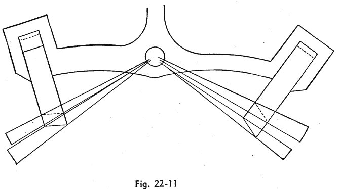
Figure 22-11 will show more clearly how the difference in the lift is produced. The pallets
have both stones shown in two positions. The position with regard to the receiving stone is identical with that shown in figure 22-10. The dotted lines indicating the face and back of the stone correspond with C, figure 22-10, and the full lines with B in the same figure. In the discharging stone the same conditions are indicated by dotted and by full lines. This figure shows clearly that drawing out the receiving stone increases impulse, while drawing out the discharging stone decreases it.
|
SEC. 409 -- Draft
|
The draft of an escapement is that power which draws the fork away from the roller after it has delivered an impulse. It is secured by setting the pallet stones at such an angle in relation to the direction in which the force exercised against the locking face that it will draw the fork against the banking.
The term resisted is used for the reason that a misunderstanding on this point prevails to some extent.
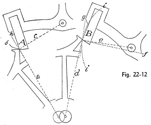
The draft is determined by the inclination of the locking face of a pallet stone from a line drawn at right angles to a radius from the pallet center to the point of contact between the locking corner of the wheel tooth and the locking face of the pallet stone. Figure 22-12 will make this detailed explanation of draft more clear.
At A is shown what is known as Tangential Locking. In this form the broken radial line a from the wheel center to the locking point b forms a right angle with the broken line c, from the pallet center to the same point. In the form shown at B, the broken radial lines d and e do not form a right angle. This is known as non-tangential locking.
In the former case the force exercised by the escape wheel is directly towards the pallet center and the resistance to that force is precisely on the same line. In the latter case the force is directed as indicated by the dotted line f, while it is resisted in the direction of the broken line e. In other words, at the tangential locking the force and the resistance are on the same lines, while at b non-tangential the force and the resistance are on different lines. The resistance being in the same direction in both cases, the draft angle must be relation to a radial line from the center of the pallets to the locking point.
|
|
The dotted line g is termed the tangential line, meaning that touches the arc ii at the intersection of the radial line e. The draft angle is laid out from this tangential line. In the escapement shown at A, the broken radial line a is continued by the full line h in order to show that the tangential and the radial lines are in this case identical.
Insufficient draft is a serious error. Where it exists there is a constant liability that when the watch is subjected to some sudden motion, the fork will leave the banking and strike the safety edge of the roller, thus retarding the motion of the balance. It is a of time to attempt adjusting a watch having this fault.
A common method of testing the draft of an escapement is to lay the watch in a horizontal position, then draw the fork slightly away from the banking and see that it returns to its original position. It is advisable to try the banking under the most unfavorable conditions to which the is likely to be subjected in its owner.s possession. First, see that the watch is let down to the point it would have reached after a run of 24 hours, then hold the watch in a vertical position. If the fork is poised it will make no difference in what position the watch is held as long as it is vertical, but if the fork is unpoised it should be held with the heaviest part lying in a horizontal line with its center. If the fork is without a counterpoise the arm would then be horizontal. In this case first try the fork by drawing it slightly away from the banking while the fork is in horizontal position to the right. This will usually be on the receiving stone. Then turn the fork to the left which will be on the discharging stone. The object of using this method is to insure against insufficient draft. If the draft is not sufficient to draw the fork against the banking under the conditions stated, it should be increased.
It is rarely that an escapement is found With too much draft. Should there be a suspicion that such is the case it can be easily determined: Take a small piece of Wax and attach it to the fork by inserting it on the guard pin or by any other method that may suggest itself; then try the draft as before. Judgment will dictate the additional weight that should overcome the draft.
Draft can sometimes be changed by tilting a pallet stone in its slot. This, however, cannot be done when the stone is closely fitted. Another method by which the draft may be altered is by pushing in one stone and drawing out the other. Drawing out the receiving and pushing in the discharging stones increases the draft on both stones. Drawing out the discharging and pushing in the receiving stones decreases the draft on both stones. That is, drawing out the receiving stone causes an escaped tooth to drop farther upon the locking face of the discharging stone, which of course increases the draft on the discharging stone, but it also increases the lock, which must be remedied by pushing in the discharging stone. This causes a tooth to drop farther down on the receiving stone, increasing the draft. A slight movement of the stone in or out will change the draft to a considerable extent. In changing a draft by this method extreme care should be used to avoid introducing other errors.
It should be borne in mind that drawing a receiving stone increases the drop on the discharging stone, but does not alter the drop on the receiving, but in pushing in the discharging stone to correct the lock, the drop is decreased on the receiving stone.
It should also be borne in mind that drawing out the receiving stone increases the divergence of the impulse face of the wheel with that stone, and that pushing in the discharging stone creases the divergence on that stone in the same manner.
That is, drawing out the receiver and pushing in the discharger increases the divergence on both stones.
Pushing in the receiver and drawing out the discharger decreases it.
When the draft is altered by pushing and pulling the stones, that operation puts the fork out of angle, which must be corrected by bending. Later on in this Work, directions will be given for making a drawing of an escapement.
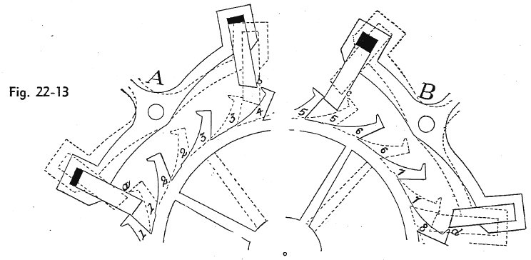
Figure 22-13 shows effect on the drop of moving a stone. At A the pallets and wheel are shown in two relative positions. In the first position they are shown in full lines and the teeth marked 1, 2, 3, 4. The will move forward when a tooth is released by the receiving stone. The pallets are then in the position shown in dotted lines and the wheel teeth, in dotted lines, are marked 1, 2, 3. In the drawing shown at A the drop is equal. The distance between the releasing corners of the receiving stone and tooth 1, as shown at a, is exactly the same as the distance between the releasing corners at b.
Now referring to the pallets shown at B, it will be observed that the receiving stone has been drawn out, as indicated by the black space in the pallet slot, and that the discharging stone has been pushed in, as indicated by the disappearance of the black space that was shown in the discharging stone slot in pallets A. At B the escapement is shown under the same conditions as at A: Lock on the receiver in full lines; on the discharger in dotted lines. It will be plainly seen that the distance between the releasing corners at c is greater than at d. This is to say that while the lock was equal with the stones in position, as at A, drawing out the receiving stone and pushing in the discharging made them unequal, as at B.
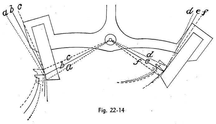
Figure 22-14 shows a pair of pallets with escape wheel teeth in three positions on each stone. The three positions are indicated by the wheel teeth shown in dotted lines and in broken lines. From the points of contact are drawn dotted, broken, and full lines running radially to the pallet center and at right angles to the radii. These lines are marked a, b, c on the receiving side and d, e, f on the discharging side. The inclination of the locking faces of the stones toward these lines determines the draft. The drawing is for the purpose of showing the opposite effects produced by moving a receiving stone from that produced by moving a discharging stone. Referring to figure 22-14, it must be evident to the observer that the farther up the locking takes place on the receiving stone the less will be the draft, and that the further up it takes place on the locking face of the discharging stone the greater will be the draft.
In case the foregoing is not perfectly clear to the student, let him suppose the tooth locked on the receiving stone at the junction of the lines cc and that a tooth dropped on the discharging stone at the junction of the lines ff. In this position the draft will be represented by the angle formed between the locking faces of the stones and the lines c and f, respectively. Now if -- leaving the wheel as it is -- we draw out the receiving stone until its locking corner coincides with the junction of the lines aa, we have not changed the draft; but when the stone is thus drawn out the pallets will have to swing further to release the tooth, with the result that the lock will now take place on the discharging stone at the junction of the lines dd. Thus it would be seen that the moving of a stone does not alter the draft on it, but on the opposite stone.
SEC. 410 -- Lock
Lock is the distance from the locking corner of a pallet stone to the point at which the wheel strikes it at the instant it drops. It should be as little as possible, consistent with the proper allowance which should be made to cover certain unavoidable mechanical defects, such as side-shake in the pivot holes, inaccuracy in the escape wheel teeth, etc The amount of lock measured in angular distance is about three-quarters of a degree. In actual measurement it would be, on a 16 or 18 size escapement, 2 to 3 hundredths of a millimeter.
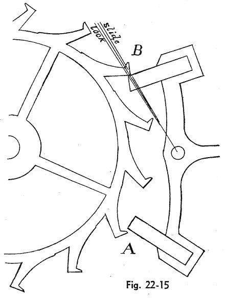
Figure 22-15 will give an idea of this amount in proportion to the size of the escapement.
Moving one pallet stone either outward or inward alters the lock on both stones. While it does not alter them exactly in the same proportion, yet the difference is trifling for ordinary alterations of this nature. In equi-distant center escapements, when the lock is equal as to angular measurement, it will be slightly greater in actual measurement on the receiving stone than on the dmscharger. This is due to the fact that the locking face of the receiving stone is farther from the center of the pallet than the locking face of the discharging stone. Judgment should be used when making an alteration for lock. Bear in mind what has been said in reference to the effect, in other particulars, of moving a stone.
SEC. 411 -- Slide
Slide -- sometimes called run -- is the distance from the point at which the wheel tooth strikes the locking face of a stone at the instant of drop to the point it reaches when the motion of the pallet is arrested by the fork coming in contact with the banking. The purpose of the slide is to allow proper freedom for the impulse pin to pass out of the fork slot; also, freedom between the guard pin and the edge of the roller. Its amount should be about the same as the lock. Figure 22-15 shows both lock and slide on the receiving stone as indicated by the lines radiating from the pallet center.
|
|
Lock and slide, in combination, are sometimes referred to as total lock. This term seems confusing as it necessitates the use of the two terms lock and total lock. It leads to a confusion of terms. Lock and slide are two distinct functions. Opening or closing a banking alters the slide but does not change the lock. A pallet stone must be moved to change the lock.
Referring back to figure 22-18, it will be seen that a wheel tooth is locked on the receiving stone, but the fork is not quite in contact with the left banking. Moving it into contact will make the slide on the stone. The slide is very easily changed by moving the banking, but should never be increased beyond an amount equaling the correct lock.
SEC. 412 -- Drop
Drop is the space that the escape wheel passes through during the interval between the release of one tooth by a pallet stone and the arrest of another tooth by the opposite stone. The drop is clearly shown in figure 22-15. At the point marked A the tooth has just been released by the discharging stone; at B a tooth has contacted the locking face of the receiving stone. The space intervening between the releasing corners of tooth and stone at A exactly equals the space between the locking corner of the tooth and its point of contact with the stone at B before it dropped. This is the drop and should be alike on both stones.
Drop may be altered by spreading the stones apart or closing them. The former increases the drop from the receiving stone to the discharger and decreases the drop from the discharger to the receiver. Closing the stones has the opposite effect; hence it is seen that change made in this manner may affect a correction with a very slight movement, as its effect is always multiplied by two. Another way in which the drop may be altered is by moving a pallet stone in or out. Moving a pallet stone does not change the drop on that stone, but on the opposite one.
Moving the receiver out increases the drop on the discharger; moving the discharger out increases it on the receiver; moving it in has the opposite effect. Drop is sometimes termed inside and outside shake, meaning that when a tooth has been released by the discharging stone and another locked on the receiving, if the pallets are then swung so as to almost -- not quite -- lock, the wheel may be moved to and fro. The locking corner is arrested by the receiving stone and the releasing corner of another tooth is arrested by the discharging stone. This is called the outside shake. With a tooth just locked on the discharging stone there will be three teeth embraced by the stones and the play between them is called the inside shake.
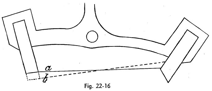
Figure 22-13 will illustrate what is meant by inside and outside shake. In both A and B the escapement in full lines shows the outside shake; that in dotted lines the inside shake. At A the lock is equal and the inside and outside shakes are equal, While at B the locks are unequal, making the outside shake close. In speaking of shake as applied to pallets, it is technically termed close inside and close outside, the former meaning that the drop is less on the discharging stone, the latter that it is less on the receiver.
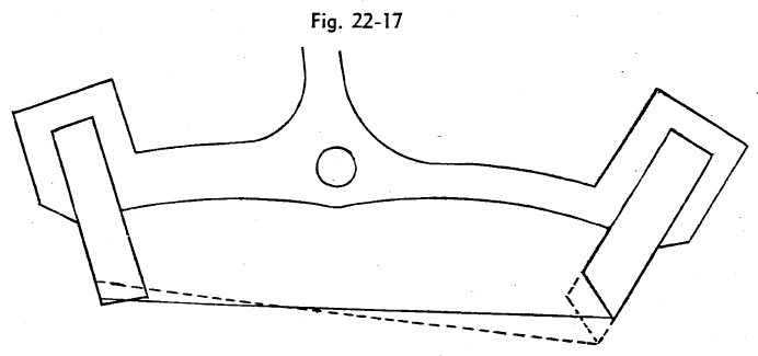
The effect upon the drop -- shake -- of moving a pallet stone is clearly demonstrated by figures 22-16 and 22-17. In figure 22-16 the full line a gives the distance that embraces three escape wheel teeth when the escapement is properly locked on the discharging stone. The broken line b gives the distance when the receiving stone has been drawn out to the position shown in dotted lines. This proves that drawing out the receiving stone increases the inside shake. Figure 22-17 shows the effect of drawing out the discharging stone, which decreases the outside shake, but not to so great an extent as the effect of moving the receiving stone.
SEC. 413 -- Equi-distant Locking and Equi-distant Center Escapement
It is well that the student should learn the precise meaning of the above terms and the different conditions they produce. They apply solely to the pallet.
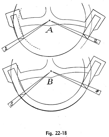
Figure 22-18 shows both forms. At A is shown equi-distant locking. The locking corners of both stones are at equal distances from the center of the pallet as indicated by the full circular line. This feature gives the escapement its name. The releasing corner of the receiving stone is nearer the center by the distance between the broken and full circle. The releasing corner of the discharging stone is farther from the center by the distance between the dotted and the full line circle; thus it will be seen that, while the locking corners are equi-distant, the releasing corners differ in distance by double the width of the stone.
At B is shown the equi-distant center escapement. In this drawing two full circular lines are drawn from the pallet center. The locking corner of the receiving stone and the releasing corner of the discharging stone are at equal distances from the pallet center. The same is the case with the locking corner of the discharging stone and the releasing corner of the receiving. This brings the centers of the impulse faces equi-distant from the pallet center, which gives this escapement its name.
As has been explained, the lift -- the angular impulse -- is measured from the pallet center. It is shown at A as indicated by lines embracing the angles 1 and 2. It will be noticed that the impulse face of the discharging stone forms a greater angle with its locking face than the impulse face of the receiving stone does with its locking face. At B the angles 3 and 4, determining the impulse angles of the stone, are the same as 1 and 2, but in this case the impulse faces form equal angles with the locking faces.
Another feature in connection with these escapements is that in the equi-distant locking the discharging stone must embrace a greater angle than the receiving. This peculiar feature will be demonstrated in the latter part of this Work when the subject of drafting an escapement is taken up.
Supplement to Section 409
Students often have trouble understanding what is meant by draft (or draw, as it is more commonly called nowadays) and how draw differs from slide. Draw is a force which cannot be seen. It is created when the teeth of the escape wheel and the pallet stones are set at such an angle as to cause the tooth to pull (or draw) the fork against the banking.
The result of draw is slide (Sec. 411), which can be seen. A simple experiment will make this relationship clear.
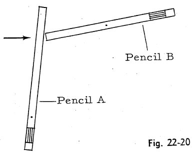
You will need two unsharpened pencils and two pins (push pins preferred). Drill a small hole through the center of one pencil and just before the eraser cap of the other. Pin the two pencils at right angles on a piece of flat board or heavy cardboard as shown below:
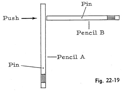
If you now try to push Pencil A towards Pencil B, as indicated by the arrow, nothing happens, because the two opposing forces are equal and cancel each other.
If you new turn both pencils slightly, so they form less than right angle as shown above at the right and again put pressure on A, both pencils will move, with B sliding down A. What you have seen is slide. The force which caused it is draw.
The angle which causes draw is set by the manufacturer of the watch, The repairman is seldom justified in changing it and normally doesn.t. What appears sometimes as a lack of draw is usually the result of improper cleaning and oiling rather than an improper angle of draw. When you replace a pallet stone, therefore, you should fit it snugly in the slot Without sideplay in order to keep the correct amount of draw.
You can test the draw with the balance out of the movement by pushing the fork away from the banking with a pointed pegwood but not to the point of unlocking. If you now lift the pegwood and release the fork, it should return promptly to the banking pin.
When the balance is in the movement, you can test draw by turning the balance wheel so the jewel is outside the fork horns. While it is in this position, push the fork away from the banking with a pointed piece of pegwood or small broach until the guard dart contacts the roller. Now take away the pegwood. If draw is present, will at once return to the banking.

 More lessons from the
Chigago School of Watchmaking course... More lessons from the
Chigago School of Watchmaking course...
|
|
|