The Chicago School of WatchmakingHome Study Course |
|
Master WatchmakingA Modern, Complete, Practical CourseLesson 6MOTOR AND JEWELED BARRELSChicago School of Watchmaking Founded 1908 by Thomas B. Sweazy Sec. 165When the mainspring breaks and its power is released all at once, there is a sharp recoil on the barrel and when this is transmitted to the train there may be pivots and teeth not strong enough to stand the blow. Before the advent of the safety pinion it was no uncommon thing to find broken or bent train pivots and teeth due to this recoil from a broken mainspring.
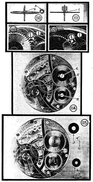
Sec. 166 - The Safety PinionThe introduction of the safety pinion protected train from this shock. This pinion is mounted on the center staff in such a way that it can turn in one direction but is held in its proper position when the power is applied from the barrel.One form is shown in figure 110, in which the pinion A is hollow and threaded to fit the threaded part of the center staff at B. When the pinion is screwed in place the power from the barrel has a tendency to tighten it on the staff. Should the mainspring break in the watch the recoil forces the barrel in the other direction and loosens the pinion from the staff allowing the barrel to spin without damage to the teeth or pivots. In figure 111 the pinion is shown in about the position it would assume when driven off by the recoil of a broken mainspring. Before replacing in the watch the pinion should be screwed down to the shoulder at C. Later the motor barrel of the type shown in the next section was introduced and this too protects the train from the shock of a broken mainspring, in fact it is sometimes called the safety barrel.
Sec. 167 - The Moter BarrelIn the going barrel as we learned in our previous the teeth for the first Wheel of the Watch train are cut in the barrel making it the first Wheel of the Watch. In the motor barrel shown here, the barrel and first wheel are two separate parts and are connected to each other by the mainspring - one end of the mainspring being hooked to the barrel and the other end to the first wheel.A very good example for the students first work in this type of barrel is found in a Waltham 16 size movement shown in figure 114. This model is known as a three quarter plate movement as opposed to the older full plate model used in our last lesson and is much easier for the beginner take down and reassemble. Practically all pocket watches now are either three quarter plate or bridge models.
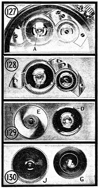
Sec. 168 - Recoiling ClickThis movement has exposed winding wheels with a recoiling click. The advantage of this style is that after winding as far as possible the click allows the ratchet wheel to back up and the coils of the mainspring are not drawn too tightly together. With the click shown in our last lesson in figure 90 it is possible to wind the coils of the mainspring so closely together that there is a sort of adhesion produced by friction on each other and the balance does not attain a full motion until the watch has run long enough to loosen these coils.In figure 112 is shown this recoiling click, over twice its actual size, just ready to drop off the tooth of the ratchet Wheel. After it has dropped into the space at D the power of the mainspring pulls it back as shown E figure 113 and F figure 114, thus allowing the ratchet wheel to .recoil. or back up slightly after having been wound to its highest point.
Sec. 169 - Replacing a Mainspring in Motor Barrel
The barrel with the first wheel is easily lifted out as shown in figure 118. It is seen turned over with the steel barrel, V, uppermost. The barrel arbor may be lifted out or it could have been removed when in the position shown in figure 117, by grasping the barrel arbor with a pair of tweezers and lifting straight up.
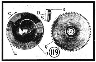
Sec. 171 - Disengage Inner End of MainspringTake hold of the barrel with one hand and the wheel with the other and disengage the inner end of the mainspring by twisting toward the right. In figure 119 is shown an enlarged view of the barrel at 0 with the mainspring in place, the barrel arbor at D and the first wheel or main wheel at Q. The mainspring has a hole end that slips over the hook in the barrel at E. As explained before this type of mainspring should be bent to a shorter curve right at the tip in order to keep it from pulling off the hook. bend can be seen at E.
The hub at X with its hook for the inner end of the mainspring at F instead of being secured to the barrel arbor is fastened to the first wheel.
Sec. 172 - Ratchet Wheel, Arbor and Barrel, Turn As One PieceWhen the ratchet wheel L figure 115 is turned in winding the watch it turns the arbor, the upper square of the arbor at R figure 116 being held in the square hole in the ratchet wheel at Q figure 164. The arbor extending through and turning on the inside of the first wheel at Z figure 119 also turns the barrel in the direction of the arrow C.The inner end of the mainspring being hooked to the hub on the first wheel at F is held still as the barrel revolves in winding and the mainspring is wound around the hub at X and, the power is applied to the first wheel from this hub. If the mainspring breaks the recoil is taken through the barrel and ratchet wheel rather than through the first wheel and train, consequently no shock is transmitted through the train to the injury of the smaller parts. In replacing a mainspring in this model select a barrel in your winder of the proper size to fit this steel barrel and wind in your mainspring, leaving enough of the tip protruding, to hook easily into the watch barrel, and transfer from the winding barrel to the watch barrel. Notice that this mainspring is coiled to the left in the barrel. Shape the inner end to fit closely around the hub on the first wheel, testing it to see that it is hooked, and then oil your mainspring as in the going barrel. Adjust the hole in the first wheel until it; is directly over the square hole in the barrel and put a small amount of clock oil on the part D, slip the arbor into position and manipulate by grasping the square at R with a pair of tweezers, until the lower square end slips into the square hole in the barrel and it will appear as shown in figure 118.
Sec. 173 - Assembling This Type.Assemble these parts by reversing the process of taking down, set the barrel in its position as in figure 117 being careful not to allow the lower square of the arbor at S figure 119 to Slip out of the square hole in the barrel at T.Replace the barrel bridge and set the screws as in figure 116. With your oiler place a small amount of clock oil where the upper end of the barrel arbor comes through the barrel bridge and also a like amount where the lower end or pivot of the arbor comes through the bottom plate. Set the crown wheel in place. Place a little clock oil in the shoulder of the crown wheel where the crown wheel washer came in contact with it. Now the crown wheel Washer in its place with the hole O figure 116 directly over the screw P. Replace the ratchet wheel with the square hole on the square of the Winding arbor and the click on the outside of the wheel as in figure 115. Place the steel discs in the proper positions and set the screws holding them in place and your movement should appear as in figure 114.
Sec. 174 - Jeweled BarrelThe addition of jewels for bearings in watches in place of the metal bushings which were formerly used has been a great factor in reducing the frictionfound in the train and escapement. Many of the uninitiated get the idea that the jewels are placed in a watch merely for their intrinsic and ornamental value, the same as diamonds in a watch case.This is not the reason but rather on account of their extreme hardness and the fine polish that can be given to them are they used as bearings to reduce the friction of the pivots. The hole jewels used for this purpose in the train are made of hard stone such as ruby, sapphire or garnet. Each has a hole drilled through it, this hole being highly polished and of a diameter to fit the pivot for which it is intended. As jewels became popular in watches, customers were inclined to judge the value of a watch by the number of jewels that it contained. Some manufacturers endeavoring to get as many jewels as possible in their watches placed jewels at each end of the barrel arbor, these jewels being set in the upper and lower plates. If you will refer to section 137 in lesson 5 you can see that the only time such jewels would reduce friction would be in winding the because the barrel arbor in the type of barrel then in use, that is the going barrel, turns only when the watch is being wound. However, with the introduction of the motor barrel it became possible to use jewels that would actually reduce the friction on these heavier parts when the Watch was running.
Sec. 175 - Waltham Jeweled Barrel
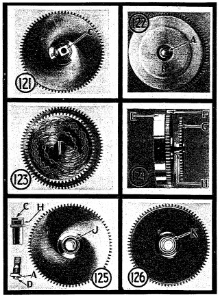
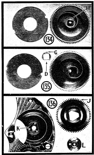
Grasp the barrel part E in one hand and the ratchet wheel G in the other and twist to the left, just as you would in taking off the screw bezel of a watch case. When you do this the upper portion of the barrel arbor may be removed with the ratchet wheel while the lower part will come out of the barrel section. The jewels are set in the main wheel, one of them being in the upper part as indicated by the arrow at J figure 125, and the other one in the lower part of the hub as shown at K in figure 126. In replacing a mainspring we go through the same operation that We did in replacing one in the motor barrel shown in figure 119.
Sec. 176 - Howard Barrel with Jewels
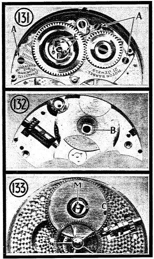
Sec. 177 - Illinois BarrelIn figure 131 is shown the barrel bridge of a 16 size Illinois movement in its position on the lower plate, together with the ratchet and crown wheel.
In replacing the barrel bridge with ratchet unit attached as shown in figure 132 and with the barrel in its place on the lower plate as in figure 133, come down from the top with the barrel bridge with the square B over the motor barrel staff at M and gently press on the barrel bridge. See that your center wheel and pinion is in place and with your tweezers revolve the ratchet wheel and the parts should fall together easily. Place the barrel bridge screws in place, tighten down and your assembly is complete.
Sec. 178 - Hamilton Barrel with Jewels
Sec. 179 - Earning While LearningHaving mastered this and the preceding you may feel inclined to realize some returns on your knowledge thus acquired. This, of course, depends upon your ability, previous experience, and the circumstances under which you work. Some states require you to be a registered watchmaker before you enter the field of watchmaking. In others, you can do work if you are an apprentice under the supervision of a watchmaker who is registered. (The laws vary in license states.) In most states, watch repairing, like many other fields, is open to the individual.s talent and does not require a license.This does not imply that an incompetent workman can succeed. Your best chance for success rests upon your ability to do expert watch repairing and to give the public its money.s worth. Because you have satisfactorily progressed with your lessons to this point, it does not follow that you now are qualified to handle all watch repair work. Trying to do all kinds of repair at this time may easily lead to trouble and dissatisfied customers. It is better to wait until you are further trained to make general repairs. Remember, the person who carries a watch wants the same time keeping qualities it had when it came from the factory. Most of all, he wants reliable service at a fair price rather than inferior work at cut rates. Be fair to your customer and to yourself. If you are not able to make repairs for people, however much you would like to, explain your reasons to them. You won.t hurt their feelings but you might hurt their watch. If you are in a position to accept minor repairs, do not attempt anything with which you are not familiar.
Sec. 181 - Learn the Vocabulary of Your VocationMake it a point to become familiar with the proper technical or trade names of the different parts of a watch so that you can talk of them with other members of the trade and make yourself understood. It is no uncommon thing to hear of a .ring. on a watch case when .bow. is meant, .shaft. for .balance staff., .chain drive. for .fusse., .Face. for .Dial., etc.In these lessons be sure you know the proper pronunciation of the words used. Do not pronounce bow as you would the bow of a ship but rather as you would in bow and arrow. In this new vocabulary which you are learning, make use of your dictionary. Look up the pronunciation of each new word and then memorize it. Make it a habit to talk about your work with your friends and members of your family and in your conversation use these new words. See if they know the correct names used in describing parts of a watch but do not go beyond your own depth! Keep on the safe side and discuss only that with which you are thoroughly familiar. In other words, don.t discuss Escapements while you are still studying Mainsprings in watches.
Looking ForwardIn the lessons so far it has been taken for granted that the mainspring in each practice watch was of correct dimensions for that particular movement but in the next lesson you will be taught the methods of selecting mainsprings and also shown some interesting experiments relating to the proper length required to get the most service from them. Your lesson will include several charts showing the Dennison and Metric measurements along with an illustration of each tip on 135 mainsprings. These charts will help you select mainsprings for American Watches. For Swiss and other American mainsprings not listed, use a material catalog.
|
||||||||||||||||

Member of the American Watchmakers-Clockmakers Institute |
|
||
|
|
|||
Comments to jsexton@agora.rdrop.com , or back to Jeff's home page...


 More
More