In Admiration of Music
(and the Dali motto)
 Audio,
especially hi-fi audio, has an unusually low amount of clarity as to what works
well. Audio design is fairly well understood but there's little, if any,
end to end discussion of how an audio playback system performs. This lack
of data on how audio components behave under typical use makes it difficult to
assess how much any one change might affect the business of transforming some
sort of recording to something you hear with your ears. The engineering is
complicated by some not so great design decisions which, unfortunately, became
standard practice. The performance assessment is complicated by the people
doing the listening being, well, people.
Audio,
especially hi-fi audio, has an unusually low amount of clarity as to what works
well. Audio design is fairly well understood but there's little, if any,
end to end discussion of how an audio playback system performs. This lack
of data on how audio components behave under typical use makes it difficult to
assess how much any one change might affect the business of transforming some
sort of recording to something you hear with your ears. The engineering is
complicated by some not so great design decisions which, unfortunately, became
standard practice. The performance assessment is complicated by the people
doing the listening being, well, people.
The greater the fidelity, the smaller the details of interest become.
Perceptual effects matter as much or more than engineering quality. To my
knowledge, the current state of the art in investigating engineering versus
subjectivity is Harman
Kardon's research. Its conclusion is people reliably choose good
measured audio performance, provided they're unaware of other attributes like
size and finish. While the data from such double blind experiments is
pretty useful, it remains PA and, especially, home audio systems are
not used in blind environments. I personally am not all that interested in
questions such as whether an alpi finish is better than thermoplastic, so this page
tends to be more about
audio engineering than subjective experience.
The audio playback chain consists of some sort of source followed by a
preamplifer, power amplifier, speaker, and the listening environment. Most
of the variables are in the listening environment, which is usually some sort of
room. Rooms come in lots of shapes and sizes with many different things in
them. Electronics and speakers are simpler. Room response tends to
dominate the listening experience below the Schroeder frequency (around 300 Hz
for most rooms, about the bottom of the
trebel clef) but there's well defined best practice for speaker,
listener, and treatment positioning to use as a starting point. As of
this writing, measurement of room response is becoming increasingly common in
making corrections, but trial and error remains the
dominant method. Monopole
and dipole speakers are less sensitive to room reflections than
conventional box speakers. At present such designs are uncommon but may
become more prevalent as a way of reducing the need for correction. Above
the Schroeder frequency speakers and electronics tend to dominate
and best practices are also well defined. However, I'm not aware of any
location other this page which consolidates such
information. While manufacturers usually publish only very limited
specification data, it's important to recognize distortion and other fidelity
errors are functions of both frequency and amplitude. Performance
specifications on electronics are generally for best case situations. Speaker performance is largely unspecified but
anecdotal information tends to be for situations
near worst case. Broadly speaking, electronics get better as signal levels
increase and frequencies decrease. Speakers get better as signal levels
decrease and frequencies increase. At typical listening levels the
performance of the two is roughly comparable, which is why electronics and
speaker selection are both significant in the audio system's overall
performance.
In the absence of good performance data—or the measurement equipment needed
to get the data—the simple solution is to fall back on listening tests.
Since such tests are rarely blind the resulting data is noisy and complicates a
selection problem often already made difficult by unfamiliarity with how audio
systems work. Common listening levels are 60 to 70 dB SPL and, in typical
home environments, require the power amplifiers deliver a few tens of milliwatts
to the speaker (if you find this surprising, do the math for a pair of speakers
with 88 dB sensitivity to deliver 65 dB SPL at three meters—the answer is
20 mW RMS per speaker, ignoring reflections). Crest factors (the ratio of peak power required by transients
to nominal signal power) range from 10 to 20 dB, creating peak output powers of
a few hundred to a couple watts per channel. So there's no need for a power amplifier to support
output four
orders of magnitude above typical listening levels. Since power amplifiers
exhibit peak performance near peak output power, performance at typical
listening levels is reduced. I am not aware of any power amplifier for
which such information is published, but IMD, THD+N, and similar
characterization data is available for chipamps. An example is National
Semiconductor's LM3886,
which is arguably best in class at the moment with 0.03 % THD+N for 20 mW at 1kHz
and 0.3 % at 20kHz. Even less data is available for speakers, but any well
designed driver will be well within its small
signal region at milliwatt power levels. Typical box speakers
should operate with less than 0.1% distortion above 100–200 Hz, rising to a few percent
at the bottom of their frequency range. If cable losses, ground bounce,
and power supply artifacts are lumped into the noise term of THD+N a LM3886
based amplifier is capable of 0.5 % or better distortion plus noise across most
frequencies, limiting on woofer displacement at the low end
and electronics on the high end. This is a respectable 45 dB down, close
to the rule of thumb -50 dB threshold where artifacts become difficult to
notice. Most power amplifiers are not as good as the LM3886, though well
designed ones are comparable.
Room effects aside, four things usually get in the way of achieving this
performance.
- cable and passive crossover impedance intervening
between the power amplifiers and the drivers
- crosstalk
between woofers and tweeters
- ground bounce
between components caused by ground loops
- operating
preamplifiers and active crossovers below optimal signal levels
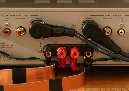
As discussed extensively below, the solution for the first two issues an active vertical
biamp combined with low impedance cabling. The second two
issues are addressed by balanced interconnects and reducing power amplifier gain—one of the odd things about audio is preamplifiers don't actually
amplify. They attenuate. Line level out of a CD player is a few
hundred millivolts RMS, but typical voltages at the drivers are
maybe 100 mV RMS. In order to achieve a couple hundred watts of output
power, power amplifiers have voltage gains around 30 dB. The
preamp therefore ends up attenuating by 50 dB, meaning RMS voltages in preamp output
stages, active crossovers, and power amp input stages are hundreds of microvolts.
This exacerbates pickup of ground bounce or supply ripple coupling into power
amp input stages and degrades op amp performance. The fix is simple; turn the power amp down and the preamp
up. In an active biamp, unity power amplifier gain generally provides
sufficient SPL and increases the SNR of most parts of the signal path by 30 dB. A
secondary benefit is op amps behind the preamplifer's volume
control operate closer to their line level sweet spot. With current
generation op amps such as the LME49740
the benefit is small compared to speaker and power stage limitations, but there
can be noticeable improvement in the volume control IC or with older op amps.
 Definitions
vary, but the range between the quietest audible sound and sound loud enough to
permanent hearing loss is about 80 dB SPL, with 75 dB or less being recommended.
The slightly loud levels commonly used for critical listening are around 60 dB.
The quietest audible sound 0 dB. So in theory ones' ears might be able to
resolve up to a 60 dB dynamic range, but in practice it seems the cochlear
amplifier achieves 20 to 50 dB depending on the type of signal and the amount of
masking. In my experience reducing things
that get in the way of the music to 40 dB down is generally pretty good, with 50
dB down becoming hard to notice and yielding diminishing returns. The list
of such things is long, perhaps even endless, but I would argue there are three main problems which limit the fidelity of off the shelf audio systems. They are
Definitions
vary, but the range between the quietest audible sound and sound loud enough to
permanent hearing loss is about 80 dB SPL, with 75 dB or less being recommended.
The slightly loud levels commonly used for critical listening are around 60 dB.
The quietest audible sound 0 dB. So in theory ones' ears might be able to
resolve up to a 60 dB dynamic range, but in practice it seems the cochlear
amplifier achieves 20 to 50 dB depending on the type of signal and the amount of
masking. In my experience reducing things
that get in the way of the music to 40 dB down is generally pretty good, with 50
dB down becoming hard to notice and yielding diminishing returns. The list
of such things is long, perhaps even endless, but I would argue there are three main problems which limit the fidelity of off the shelf audio systems. They are
- ground bounce and ground loops
As discussed in the section on interconnects
below, ground voltages differ between components. Various things
can be done to minimize this, but the simplest, easiest, safest, and (in pro
audio) most common solution is to use balanced interconnects between the
preamplifer (or active crossover) and power amplifiers. Any decent differential receiver has
40 dB of common mode rejection, enough to reduce artifacts from ground
current to 40 dB or more below signal level.
- passive crossover and speaker cable impedance
The more stuff there is between the power amp and the speaker drivers the
harder it is for the power amp to control the drivers. The electrical
measure of stuff is impedance, and most of this page is devoted to
discussing how to get the impedance between the amp and drivers to 50 dB or
more below the driver's impedance by use of an active vertical biamp.
- room effects
Make the effort to position speakers a meter or more away from walls and
experiment with basic room treatment to mitigate undesirable reflections and
resonances. In my experience, non-audiophile treatments like hanging a rug on a wall or
using a ficus tree as a base trap often work just fine (and tend to look
better).
Unfortunately, the availability of balanced interconnects, low gain
amplifiers, and active crossovers in hi fi audio is very limited.
Fortunately, these are common in professional audio gear, so consider active studio monitors
instead of conventional power amps and speakers. Another noteworthy option
is Siegfried Linkwitz's active speaker designs.
Sadly, there aren't many reasonably priced preamps with balanced outputs.
 Assuming you have two way speakers, the five most interesting wiring topologies
are
Assuming you have two way speakers, the five most interesting wiring topologies
are
- monowire
A single cable connects one channel of a stereo power
amp to a single speaker. The speaker's high and low frequency sections
are shorted together at the speaker. Optimal positioning of the power
amp is midway between the speakers with equal length cable runs to both
speakers.
- biwire
One cable connects one channel of a stereo power amp to
the speaker's high frequency section. Another cable connects the
same channel to the speaker's low frequency section. The speaker's
trebel and bass sections are shorted together at the amplifier.
Optimal positioning of the power amp is midway between the speakers with
equal length cable runs to both speakers.
- horizontal biamp
One cable connects a one channel of a
stereo power amp to the speaker's high frequency section.
Another cable connects one channel of another stereo power amp to the
speaker's low frequency section. The speaker's channels are not
shorted together. Optimal positioning of the two power amps is
midway between the speakers with equal length cable runs to both
speakers. The two power amps need not be identical, but not all
combinations of amplifiers work well.
- vertical biamp
One cable connects a one channel of a
stereo power amp to the speaker's high frequency section.
Another cable connects the other channel of the same stereo power amp to the
speaker's low frequency section. Optimal positioning of power amp is
directly behind the speaker with very short cables between the amp's binding
posts and the speaker's binding posts. The two power amps should be
identical.
- dual monoblock
Each speaker is driven by a mono power amp.
Optimal positioning of the power amp is the same as for a passive vertical
biamp and the two monoblocks should be identical.
The reason biwiring may improve sound quality is back EMF
from the woofers. In a typical speaker, the low frequency section consists
of a bass woofer and a midrange woofer. The high frequency section is
usually a single tweeter. As woofer signal levels tend to be 20 dB
higher than the tweeter levels even low amplitude EMF residuals coupled over to
the tweeter through the crossover can have a noticeable effect. Whether or not
the coupling is a
problem depends on how large the back EMF is, the amount of attenuation the
crossover provides, and the power spectral density of the music played. Biwiring reduces back EMF effects by interposing the impedance
of two runs of speaker
cable between the speaker's high and low frequency stages. Since a solid state power amp's output impedance is
typically under 0.1 mΩ, this change is usually a significant rebalancing of the
network. Instead of
the inputs of the speaker's trebel section seeing the full back EMF voltage, most
of the back EMF is absorbed by the amplifier before it gets to the trebel
section's terminals. Exactly how much
attenuation this provides depends on the speaker, amplifier, cabling, and
frequency of interest, but it's usually around 30 dB or so. Tube amps,
with output impedances of 1 Ω or more, have less to offer in
a biwire. Unfortunately, information about a particular speaker's back EMF handling is seldom available. The easiest reliable way to find out if
biwiring or biamping will improve the speaker's sound by reducing back EMF
effects is to borrow a friend's cables, try it, and see how
much improvement results. Your mileage will vary. If you're lucky,
your speaker manual might have a hint in it like Dali's low key statement "bi-wiring or bi-amping is
recommended".
From time to time I get emails saying biwiring cannot possibly
make any difference in the sound quality. Typically, these folks make two
mistakes. One is treating cabling as lossless. The other is
neglecting the inertia of the driver generating current in the voice
coils. A correct Spice model includes cable RLC parameters and a
representation of mechanically stored energy in the drivers (a controlled source
or the like). Without them, the
model yields erroneous results.
Biamping eliminates back EMF coupling, but its primary advantage is it allows
the use of active crossovers and shorter speaker cables. As the following sections
discuss, these offer dramatic improvements in how much control the power
amplifier has over the drivers. Dual
monoblock or passive vertical biamps require an identical pair of amplifiers in
order to maintain phase coherency between the two speakers. Different
amplifiers have slightly different response times and slightly different
responses. Ears are discriminating enough to hear the resulting differences
between the left and right channels if different amps are used on different
speakers. In my experience, the result is usually mushy sound that is worse than just picking one of the amps and running a monowire.
Horizontal biamping doesn't have this problem because the same amplifier
drives the same section of both speakers. As a result, the left and right
high frequency stages are consistent, as are the low frequency stages. Horizontal
biamps can still have problems with the low frequency sections leading or lagging the
high frequency sections (I personally find lagging sounds better but gets a
little silly when the bass seems to be coming from the next block over). Also, differences in amp response around the
speakers' crossover frequency can cause burrs or other artifacts in the
sound. So getting the most out of a horizontal biamp means using identical
amps, at which point one might as well run a vertical biamp and take advantaged
of the reduced speaker cable length it offers.
The passive in passive horizontal and passive vertical biamping comes from
the use of the passive crossover in the speakers. Rod
Elliott discusses the inefficiencies and problems of passive biamping and
the advantages of using an active crossover upstream of the power amps. Unfortunately commercially available speakers which
come with a matched active crossover are extremely rare in the hi fi market—the ones I'm
aware of are the Dali Megalines and the Linkwitz Orion and Pluto. However,
biamped
active speakers with integrated active crossovers are readily available in the
professional audio market starting around US $300. My personal path to
audio was by way of the hi fi market, so my experience is one of working through
incremental upgrades as I learned more; I started with a monowire, then a biwire,
then a passive horizontal biamp, then a passive vertical biamp, and eventually
did surgery on my speakers to convert to an active vertical biamp. The
result is this page is backed by a fair bit of personal experience with
different options, but if I were doing it all over again I'd take a hard look at
active speakers and studio monitors for use as home audio main speakers.
It would certainly be less hassle; I don't know how many hours I've spent
soldering up incremental upgrades of speaker cables or taking apart my speakers
and figuring out what to do next. In comparison, all you have to do with
pro audio powered speakers is plug in an XLR cable.
Audio systems consist of a chain of amplifiers driving loads
through cables. The output amp of the source drives the preamp
inputs. The output amp of the preamp drives the power amp inputs.
And the output power amp drives the speakers. In each of these stages, the
load the output sees is the sum of the cable impedance and the load
impedance. The voltage drop across
the cabling relative to the voltage at the output amp is Zcable / (Zcable
+ Zload), where Zcable
is the cable impedance and Zload is the load impedance. When driving pre or power amp inputs, Zload is
large, so Zcable can be large without significantly affecting the
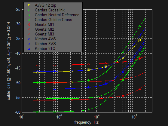
signal seen by the input. The figures below show the signal loss
on an amp with a 33 kΩ input impedance due to 1 and 2 m long interconnect
cables of a variety of types (see termination
impedance for discussion of ZT). The interconnects in the graphs are
- AWG 28 or 24 zip style "courtesy interconnects" of
the type which typically come for free with CD players
- the roughly AWG 18 zip typical
of most well made audiophile type interconnects
- AlphaCore's MicroPurl and Tourmaline interconnect cables and Goertz MI1
speaker cables
-
Kimber Hero interconnects and 4VS speaker cables
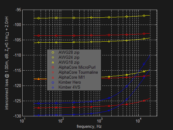
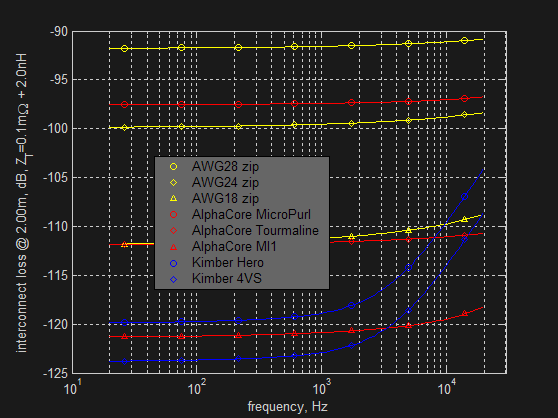
As you can see, the signal loss over even the cheapest interconnects is two orders of magnitude smaller than what ears can resolve. To put these
interconnect loss figures in perspective, the signal to noise ratio of a good CD
player and power amps is usually a bit above 110 dB and line level inputs on pre
amps are usually around 95 dB. Phono stages are typically around 75 dB.
So interconnect lossesa are two orders of magnitude smaller than what the CD can
resolve, and are comparable or even below the preamp's noise floor.
 Much ado has been made about the need for shielded interconnects. There is no strong case for shielding.
Skin depths are large at audio frequencies (roughly 5 mm in copper at 200 Hz), so shielding has to be quite
thick to result in significant attenuation. Canceling the field via twisted pair
is much easier than milling shields out of copper or aluminum bar stock. Where
shielding may make a difference is with AM radio interference,
since noise picked up at the upper end of the amplifier's frequency could be
coupled down into the audible range through intermodulation products. Such
coupled noise is typically in the microvolt range and is attenuated by 40+ dB
in intermodulation, putting it well below the noise floor
of a good power amp or CD player. Even if you live in the near field of an
AM radio station the incident field will be quasistatic over the length of
a twisted pair interconnect and is therefore easily cancelled without a shield.
Much ado has been made about the need for shielded interconnects. There is no strong case for shielding.
Skin depths are large at audio frequencies (roughly 5 mm in copper at 200 Hz), so shielding has to be quite
thick to result in significant attenuation. Canceling the field via twisted pair
is much easier than milling shields out of copper or aluminum bar stock. Where
shielding may make a difference is with AM radio interference,
since noise picked up at the upper end of the amplifier's frequency could be
coupled down into the audible range through intermodulation products. Such
coupled noise is typically in the microvolt range and is attenuated by 40+ dB
in intermodulation, putting it well below the noise floor
of a good power amp or CD player. Even if you live in the near field of an
AM radio station the incident field will be quasistatic over the length of
a twisted pair interconnect and is therefore easily cancelled without a shield.
There is, however, one noise source which is relevant to interconnects.
Differences in the ground voltage between components cause a different signal to
be seen at the input of a pre or power amp than was provided at the source or
preamp output. The resulting noise in the input signal is commonly assumed
to be due to the ground loop formed between components and various remedies such
as ground lifts exist to attempt to cut the loop. These are effective in
cases where there really is significant loop current, but a more typical
situation is having all components plugged into the same power strip. This
is a star ground topology, with the most convenient reference being the power strip and ground
bounce at the components being proportional to variation in supply current
drawn. Since they drive high impedance loads, ground bounce in sources and
preamplifiers is several orders of magnitude smaller than power amp bounce.
In my experience, it has negligible effect on audio quality. However, power
amplifier ground bounce is usually significant. The amount of bounce
depends on the amplifier's supply ripple current variation in response to
varying output and the power cord and transformer impedance the ripple current
passes through. Usually, the dominant term is the transformer's leakage
inductance which, being on the order of 10 mH for a typical
toroid at typical ripple frequencies, produces a noise figure in the
vicinity of 40 dB down from the transient output voltage. How much this
matters depends on the power amplifier's voltage gain. For typical gains
of 20 to 30 dB it's significant as it's only 10 or 20 dB below the input signal
from the preamp. At unity gain it's likely 40 dB down, which is noticeable
but rarely dramatic. If the amplifier is attenuating, ground bounce can be
50+ dB down. This may make it negligible, provided all the bypassing and
leakage inductances line up right and there's a reasonable return path for the
flux leaked from the transformer. The structure of the return path is
complicated due to the ubiquity of grounds, variation in use of green wire
ground, interconnect structure, and so on, but my experience is the neutral to
green wire loop usually puts a few milliohms in parallel in the case when green
wire is DC coupled to secondary ground. Not ideal, but not too bad either
as loop load impedance is roughly comparable to leakage inductance source
impedance. Other ground topologies generally increase the load impedance,
allowing more ground bounce to develop. Ground lifts may allow components
to float enough to mitigate this but suffer from offset voltages due to current
returning through interconnect grounds.
A more robust solution is to mitigate ground bounce with balanced interconnects. Differential inputs usually have at least 40 dB of common
mode rejection which, since ground bounce is common mode, puts ground bounce
artifacts 50 dB below signal level even if the power amp has 30 dB gain. In comparison,
unbalanced inputs force the receiver to have 0 dB of
rejection. A surprising consequence is ground bounce developed over the
power cord is audible in the common case of unbalanced interconnects and an
amplifier running 30 dB gain. Typical AWG 16 power cords develop ground
bounce about 70 dB down from the amplifier's output voltage. With 30 dB
gain in the amplifier and no rejection in the input, ground noise ends being 40
dB down from the input signal. Throwing copper at the power cord easily
puts the power cord component 50 dB down but, unlike balanced interconncects,
does nothing to mitigate ground bounce across the transformer.
As an aside, some interconnects are offered in copper and much more expensive
silver versions. Silver is the only metal to have higher conductivity than
copper, 63.01 MS versus 56.6 MS—a 5.7% improvement—but the silver
versions usually cost about six times much. In comparison, the reduction
in resistance by increasing one AWG gauge is right about 20% and the cost of
doing so is around an extra 20% as well. Since interconnect impedances are
negligible it doesn't actually matter, but buying heavier gauge copper has 17 times
the price performance of switching to silver. A very
few interconnects come in gold versions, which is even more ridiculous than
using silver. Gold's conductivity is 45.2 MS, or 82% of copper's. So
not only do gold cables cost 100 times as much as copper interconnects at the
same AWG, but
electrically they are worse.
 Assuming something reasonable is used, the exact choice of speaker cable is
not as significant as choice of speakers, amplifiers, or the amplification topology
used. It is, however, the next most significant factor in the system and
changes in speaker cables have distinctly audible effects. As usual, most speaker cable manufacturers don't publish specifications a handful do. This
section takes a detailed look at the differences between standard AWG 12 zip
cord, based on measurements
from an LCR analyzer, a selection of Cardas's
cables, Kimber's cables,
and Goertz's MI
series. Cardas, Kimber, and Goertz are chosen because they publish full RLC
parameters. Pear
haphazardly mentions RLC for certain cables, Nordost
publishes L and Cs in
the same range as Kimber's figures, but not R. Cobalt
publishes R and a better than average 100nH/foot, but not
C. (Kimber, to their credit, publishes full RLC figures for their interconnects too�Cardas
and Cobalt have R and C and
Goertz R, but no other manufacturer I've come across consistently makes full RLC
available.) I
don't have access to an RLC meter or samples of all of these cables, so the
published figures are taken on faith even though there may be errors or smoke
and mirrors involved. In general, there's some difficulty
reproducing manufacturer results and it's unclear how manufacturers are
accounting for termination impedance. Goertz's published inductances appear to be high by
a factor of two, which may be the result of an incorrect measurement
setup. Cardas touts their golden section stranding patent, but
the patent states it's not understand why golden section stranding
works. This calls into question whether there's anything real to the
patent or if it's just a marketing item (I personally think the
latter). But the cable models and results presented here correlate well
with my listening experiences. So the approach seems useful as a predictor
of real world cable performance.
Assuming something reasonable is used, the exact choice of speaker cable is
not as significant as choice of speakers, amplifiers, or the amplification topology
used. It is, however, the next most significant factor in the system and
changes in speaker cables have distinctly audible effects. As usual, most speaker cable manufacturers don't publish specifications a handful do. This
section takes a detailed look at the differences between standard AWG 12 zip
cord, based on measurements
from an LCR analyzer, a selection of Cardas's
cables, Kimber's cables,
and Goertz's MI
series. Cardas, Kimber, and Goertz are chosen because they publish full RLC
parameters. Pear
haphazardly mentions RLC for certain cables, Nordost
publishes L and Cs in
the same range as Kimber's figures, but not R. Cobalt
publishes R and a better than average 100nH/foot, but not
C. (Kimber, to their credit, publishes full RLC figures for their interconnects too�Cardas
and Cobalt have R and C and
Goertz R, but no other manufacturer I've come across consistently makes full RLC
available.) I
don't have access to an RLC meter or samples of all of these cables, so the
published figures are taken on faith even though there may be errors or smoke
and mirrors involved. In general, there's some difficulty
reproducing manufacturer results and it's unclear how manufacturers are
accounting for termination impedance. Goertz's published inductances appear to be high by
a factor of two, which may be the result of an incorrect measurement
setup. Cardas touts their golden section stranding patent, but
the patent states it's not understand why golden section stranding
works. This calls into question whether there's anything real to the
patent or if it's just a marketing item (I personally think the
latter). But the cable models and results presented here correlate well
with my listening experiences. So the approach seems useful as a predictor
of real world cable performance.
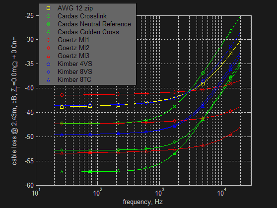
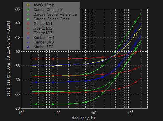
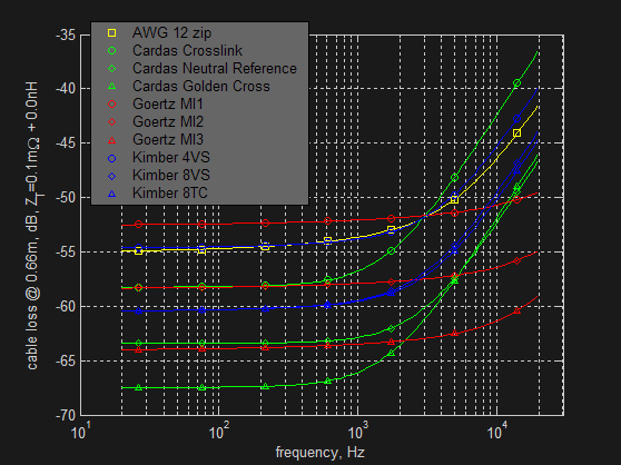
The figure below shows the cable loss for an eight foot run of these cables
as a function of frequency, eight feet being a typical cable length for monowire,
biwire, and horizontal biamp topologies. The loss calculation here is the same as described in the
interconnect section above and calculations use an RLCG cable model which
includes skin effect. Published RLC cable parameters are used and I've
included a worst case G so people who are interested in exploring how negligible
dielectric absorption really is can play with it. The Matlab source code for the analysis is
here (the code for interconnect analysis above is
basically the same, see termination impedance
for discussion of ZT). While I'm not entirely satisfied with
the skin effect integrations, stranded cables are approximated as solid wire,
and edge and back effects in low inductance planar structures are
neglected, the numbers should be accurate within a few percent, which is
probably better than the manufacturer data they're based on. An ideal 4 W
speaker is assumed. Unlike interconnects, whose loss is subsumed by the electronics' noise
floor and the limitations of your ears, speaker cable losses are well within the
audible range. Reducing the impedance between the amp and the load pays off. I've
listened to 4VS, 8VS, MI2, and
doubled MI2 (essentially the same as MI3) with 2.4 meter long cables and the roughly 6 dB improvement of 8VS
over 4VS is definitely worthwhile. It's not huge, but the 8VS has noticeably
cleaner sound, particularly with regard to transients.
The 4 dB low frequency improvement going from 8VS to doubled MI2 is similar, though not as
dramatic; high frequencies do open up noticeably. Compared to 8VS, doubled
MI2 has a smoother and more natural sound which
reveals more details and texture. I found it more relaxing to listen to as
well.
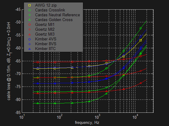
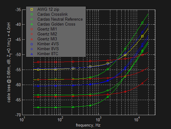
In a fully optimized vertical biwire or dual monoblock the amps' binding posts
are placed right next to the speakers' binding posts and very short cable runs
are used. This reduces cable losses by about 25 dB, as shown in the figure
below. This is a
significant improvement over nominal eight foot runs, but the change here is about the largest
possible outside of an active speaker.
A more realistic minimum cable length for a well set up monowire, biwire, or
horizontal biamp is six feet or so. This offers a modest 3 dB or so
improvement over eight foot runs and, again speaking from personal experience,
it's an improvement worth seeking out. In a vertical biamp or dual
monoblock, putting the
amps right behind the speakers is often impractical due to how the stereo is
positioned in a room or because there's need to get to the amps' power
switches. Cable runs around two feet therefore tend to be a practical
minimum distance, roughly a 12 dB improvement over eight foot
runs. I've done side by side comparisons of horizontal and vertical biamp
configurations using these cable lengths and the additional detail, texture,
tonality, and transient control of the vertical biamp is distinct. But not huge. Perhaps the best description I can think of is it's
the difference between good and great. Certainly, if one has a pair of
identical power amps, there is no reason not to run a vertical biamp or dual
monoblock, save some money
on speaker cabling, and get better performance, too (though if you're willing to
convert to an active biamp
you're better off investing in an active crossover before spending on cables).
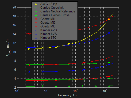
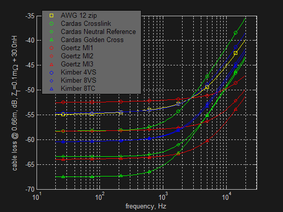
Since driver impedances are low getting a
low loss speaker cable requires the cable be quite low impedance. The figure
below shows the impedance per meter for the cables considered here. Two
effects dominate. One is the DC resistance of the cable. The other
is the cable's inductance. Reducing DC resistance is a matter of
using ever more copper. MI 1 is the equivalent of AWG 13, 4VS the
equivalent AWG 12, Crosslink is AWG 10, MI2 is AWG 10, 8VS is AWG 9, 8TC is AWG
9, Neutral Reference is AWG 8.5, MI3 is AWG 7, and Golden Cross is AWG 5.5.
The MI cables are
around 20 nH/m, whereas all the other cables are above 125nH/m. This why
the Goertz impedance curves are so much flatter than the
round wire based cables.
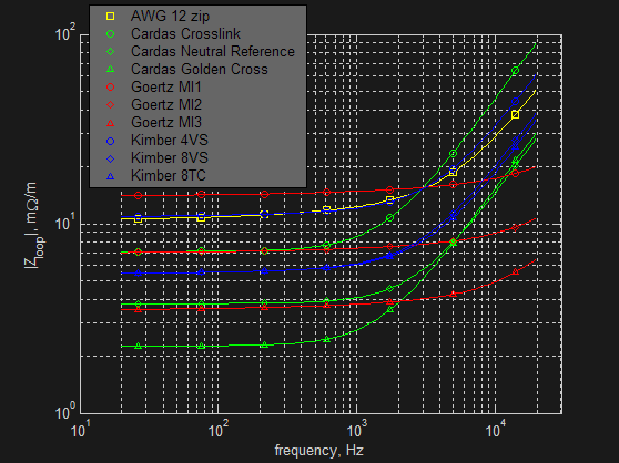
Resistance increase due to skin effect has been the subject of considerable
debate. I've yet to find an analytic skin
effect model which exhibits fully correct behavior. However, the numerical
integrations in the code linked above are trivial and exhibit convergence to DC
resistance and correct sqrt(frequency) behavior across a wide frequency
range. The resulting answer is simple; skin effect adds a few milliohms over the audio
band. This is negligible in round wire cables.
If the cable is truly low inductance, skin effect and inductance are comparable.
 Contact resistance often comes up when speaker cables are discussed. Usually, discussion centers on which form of termination—bare
wire, bananas, spades, etc.—best makes electrical contact and
therefore delivers
lowest resistance. Measurements of the contact resistance of
different audio terminations are hard to find, but contact resistance
characterizations for various platings applied to various test fixtures are not
hard to come by in technical journals. This paper on contact resistance measurements in the AMP Journal of Technology is
a good introduction. A reasonable rule of thumb for a mechanically sound
connection between ohmic metals (i.e. gold, silver, copper) is 0.5 mΩ/mm2.
Bananas and spades have significantly more than a square millimeter of contact
area. A bare wire termination which has been through several iterations of
binding post tightening and cable wiggling in order to ensure a good contact can
have a few square millimeters of good contact as well. Since the contact is
ohmic regardless of how the connection is made, the resulting resistance is on the
order of 0.1 mΩ per cable when good contact is made. This is much less than the skin effect
resistance increase or inductive impedance increase of well made cables, so
cable performance is not limited by contact resistance. (However, it's been
my experience bare wire connections have to be retightened about once a month in
order to keep the wire in good contact with the binding post—when I was using
bare wire the eventual loss of detail reminded me to tighten the binding posts; a loose
one can easily be the limiting factor in a stereo's performance.)
Contact resistance often comes up when speaker cables are discussed. Usually, discussion centers on which form of termination—bare
wire, bananas, spades, etc.—best makes electrical contact and
therefore delivers
lowest resistance. Measurements of the contact resistance of
different audio terminations are hard to find, but contact resistance
characterizations for various platings applied to various test fixtures are not
hard to come by in technical journals. This paper on contact resistance measurements in the AMP Journal of Technology is
a good introduction. A reasonable rule of thumb for a mechanically sound
connection between ohmic metals (i.e. gold, silver, copper) is 0.5 mΩ/mm2.
Bananas and spades have significantly more than a square millimeter of contact
area. A bare wire termination which has been through several iterations of
binding post tightening and cable wiggling in order to ensure a good contact can
have a few square millimeters of good contact as well. Since the contact is
ohmic regardless of how the connection is made, the resulting resistance is on the
order of 0.1 mΩ per cable when good contact is made. This is much less than the skin effect
resistance increase or inductive impedance increase of well made cables, so
cable performance is not limited by contact resistance. (However, it's been
my experience bare wire connections have to be retightened about once a month in
order to keep the wire in good contact with the binding post—when I was using
bare wire the eventual loss of detail reminded me to tighten the binding posts; a loose
one can easily be the limiting factor in a stereo's performance.)
Probably the biggest issue in speaker cable termination is the
spreading of the
conductors needed to connect the cable to power amp or speaker binding posts. Moving
conductors away from each other increases inductance and decreases capacitance,
so opening up the cable to attach to binding posts adds inductance. How much inductance is added depends on the construction
of the cable, positioning and orientation of the binding posts, and how the
cable is opened up. This obviously varies, but the
less the cable is opened up the lower the additional
inductance. A reasonable, if rough, approximation is to treat the cable as
two independent wires where it enters the binding posts. There are closed
form RLCG parameters for this structure and the result is about 1.25 μH/m
at typical binding post separations. A typical
manufacturer cable termination is a 0.20 m long taper from 150 nH/m to 1.25 μH/m
and adds around 15 nH per termination (which agrees well with the
Audioquest cable inductance measurements cited in the previous section). A
reasonably well done DIY termination
is around 4 nH, though you can do better if you get particular about
how the cable's broken out.
Termination therefore adds something like 0.2 mΩ and 5 to 30 nH of inductance to the
cabling. How much this matters depends on the cabling you're using.
Contact resistance is small compared to cable resistance in the AWG 10 range but
may have a small effects in the AWG 6 range if your speaker cables are
short. Most good speaker cables are around 125 nH/m, so an extra 30 nH is about 10%
extra for a 2 m cable run. Goertz cables are around 5 or 10 nH/m,
so 30 nH is a few times the inductance of the
cable. The figures below show the effects of a 0.1 mΩ contact
resistance, contact resistance with 4 nH of termination inductance, and contact
resistance with 10 nH of termination inductance for 0.66 m cable runs. The
loss increase due to contact resistance is small even for Golden Cross (AWG 5.5)
and Goertz MI3 (AWG 7) but a 30 nH termination inductance increases loss by
around 5 dB. In comparison, 4 nH of termination impedance increases loss
by less than 2 dB even for Goertz MI 3 (13 nH/m). Granted, these are
approximate numbers, but the implications are clear; if you want the most from
your speaker cables buy bulk cable and terminate it yourself so it's opened
up as little as possible.
Termination impedance is considerably less important for interconnects
as RCA and XLR connectors spread the cable out less
than binding posts do. A ballpark analysis similar to the one for speaker cables suggests interconnect
termination impedances are around 0.1 mΩ and 2 nH (the numbers used in the
interconnect figures above) versus typical resistances of 50 to 200 mΩ/m
and inductances around 100 nH/m.
 Even
if biamping doesn't offer improved improved sound quality
from control of back EMF, an improvement in sound quality can still
be had from a vertical biamp's ability to situate the power amps in close
proximity to the speaker's binding posts. As the sections above show,
cables can be made significantly more transparent through
construction and reduction in length. However, in a typical floorstanding
speaker there's around 1.25 meters of internal cabling between the binding posts and
the tweeter. The shorter the cabling outside the speaker, the greater the
relative length of the cable internal to the speaker becomes and the less
effective cabling optimization outside of the speaker is. Further,
internal speaker wiring is rarely of quality; in most cases AWG 12 zip cord
would be a significant step up. Short of unconventional, but obvious
optimizations—such as drilling holes in the side of the speaker and sticking
the power amp on a shelf right next to the drivers—the only thing which can be
done about the internal wiring is to open up the speaker and recable
it. By itself, recabling is somewhat pointless, since shaving off a few
hundred nH of inductance and some mΩ of resistance in internal wiring
doesn't do much compared to the Ω, μH, and μF in the speaker's passive
crossover. As a result, by far the largest optimization in the signal path between the
power amp and the speaker is removing the passive crossover. This is only
possible if you have a biamp and relocate the crossover between the preamp and
power amps (removing the crossover and running a full spectrum signal to the
speakers is likely to blow out the tweeters).
One option, which for want of a better name I call optimized passive biamping, is to
reimplement the passive crossovers with adjustment for a power amp's input
impedance instead of a speaker's. While perhaps short on elegance, such optimized passive
biamping accomplishes the key goal of getting the passive crossover out of the
power amp's way. It also allows the crossover to be rebuilt without using
power components, removing various parasitics and making it a bit easier to
build accurate filters. In the professional audio market you can find
speakers with all of this done for you, such as Mackie's HR626 studio monitors.
Even
if biamping doesn't offer improved improved sound quality
from control of back EMF, an improvement in sound quality can still
be had from a vertical biamp's ability to situate the power amps in close
proximity to the speaker's binding posts. As the sections above show,
cables can be made significantly more transparent through
construction and reduction in length. However, in a typical floorstanding
speaker there's around 1.25 meters of internal cabling between the binding posts and
the tweeter. The shorter the cabling outside the speaker, the greater the
relative length of the cable internal to the speaker becomes and the less
effective cabling optimization outside of the speaker is. Further,
internal speaker wiring is rarely of quality; in most cases AWG 12 zip cord
would be a significant step up. Short of unconventional, but obvious
optimizations—such as drilling holes in the side of the speaker and sticking
the power amp on a shelf right next to the drivers—the only thing which can be
done about the internal wiring is to open up the speaker and recable
it. By itself, recabling is somewhat pointless, since shaving off a few
hundred nH of inductance and some mΩ of resistance in internal wiring
doesn't do much compared to the Ω, μH, and μF in the speaker's passive
crossover. As a result, by far the largest optimization in the signal path between the
power amp and the speaker is removing the passive crossover. This is only
possible if you have a biamp and relocate the crossover between the preamp and
power amps (removing the crossover and running a full spectrum signal to the
speakers is likely to blow out the tweeters).
One option, which for want of a better name I call optimized passive biamping, is to
reimplement the passive crossovers with adjustment for a power amp's input
impedance instead of a speaker's. While perhaps short on elegance, such optimized passive
biamping accomplishes the key goal of getting the passive crossover out of the
power amp's way. It also allows the crossover to be rebuilt without using
power components, removing various parasitics and making it a bit easier to
build accurate filters. In the professional audio market you can find
speakers with all of this done for you, such as Mackie's HR626 studio monitors.
A better approach than optimized passive biamping is to situate an active crossover between the pre and power
amps. Power components and inductors are no longer needed, reducing
component parasitics and eliminating phase reversals at LC
resonances. An active crossover can convert
back and forth between balanced interconnects and unbalanced filtering,
eliminating the need to have two closely matched passive filters handling the
plus and minus signals of balanced interconnect. Filter and level
adjustments are more easily made since components are low power and the op amps
in the active crossover automatically compensate for varying load impedance.
The simplest way to get active crossovers is to buy active studio monitors or
PAs.
In my case, I picked up a lightly used, Ashly
XR-1001 off eBay for 10% the combined price of my pre and power
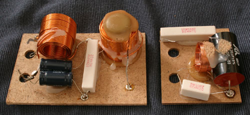
amps. Initial tests were promising, so I pulled the passive crossovers out of my Dali Suite 2.8
speakers, spent about 15 minutes fine tuning the crossover
frequency, and output levels and had a good setup. The improvement in sound quality wasn't as dramatic as the active crossover
advocates I've come across claim, but was certainly worth the price of a
used Ashly and soldering up a few more XLR interconnects. Highs
are cleaner, bass is tighter, and a remarkable amount of midrange tone was revealed as slush and
removed. Woofer sensitivity increased by 6 dB, tweeters by 9
dB. The most succinct description I can come up with is the sound
feels unplugged. It's closer to what you hear while playing as a musician
without amplification or listening to a symphony in a concert hall rather than a typical concert or stereo sound. Bass
drums go whump like they do when you tap the pedal, without the crunch or
harshness which amplification usually adds. Open high E strings ring out
the way they do when you unfret them while the guitar's hanging off your
shoulder. Individual instruments' lines are more definite and the overall sound
became noticeably more detailed. Intricate pieces or works with a lush
variety of sounds show particular improvement. Musicians' mistakes become more obvious and flaws in
recordings are revealed, too. Sorting through my collection, most
tracks laid down before the 1990s sound a bit off and some things from the 1970s
which I used to enjoy have become painful to listen to. I wouldn't say the change is for everyone;
the vintage of one's collection aside, hard rock or
metal in particular have less attack and a less harsh, more instrumental
quality. If you like your bass loud, heavy, and generally out of control you may find an active
crossover disappointing as it doesn't yield the same amped up kind of sound.
But for most genres the active crossover strikes
me as a clear improvement and I, for one, am happy to lose overemphasized drums
in exchange for
greater clarity in what a lead guitarist shreds out.
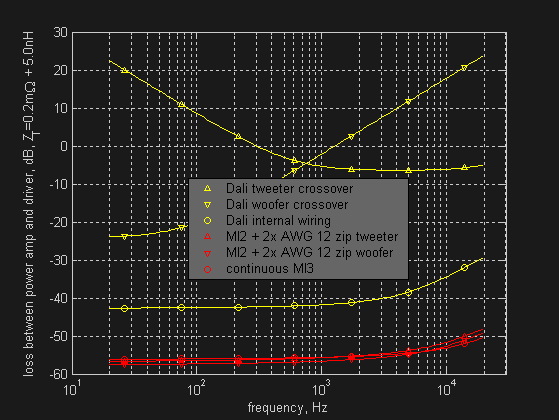
Having gotten the passive crossovers out of the way, I
upgraded the internal wiring. The figure above compares wiring options against
passive biamping and Dali's stock,wiring. In all cases a 0.66 m run of MI3 external to the speaker is
assumed and the values for passive biamping are approximate as Dali's inductors
are unlabeled and I don't have access to an inductance meter. Upgrading internal wiring offers a
14 dB improvement for woofers and 20 dB or so for the tweeters. A continuous
MI3 installation is 1 dB better than MI2 bulked up with zip cord for
tweeters and 1 dB worse for woofers. Installing continuous MI3 equivalent
cable would incur
a great deal of hassle in building new cables and
binding post panels and cost a couple hundred dollars in materials, which hardly
seemed worthwhile for 1 dB on the tweeters. So I left the binding posts in
place and ran sections of MI2 and zip between them, the power amps, and the
drivers. I was expecting
little or maybe even no noticeable improvement from changing out internal
speaker wiring, but
was pleased to discover differences comparable to other cable
improvements I've made. Nothing radical but still quite nice and, to my
ear, more of a difference than converting from a passive to an active biamp. There's more
detail throughout the woofers' range. Mids are cleaner and bass is
tighter. Highs off the tweeters are so clean my jaw dropped the first time
I heard them. The woofers seem to move a little more easily and the speakers are maybe 1 dB louder.
What struck me initially is bass crunch; you can hear the power amp shoving the
woofer coils around and stopping back EMF. But what really comes through
are dynamics. Fast paced pieces simply haul, voices have rich character,
and instruments are truly lifelike. Sound on well
done CDs from around 2000 or newer shows improvements but there's minimal
improvement with most of the professional recordings I have from the late 80s or
early 90s. As with my comments about recording dates and converting from
passive to active biamping, this is a rule of thumb and not a hard and fast
statement. For example, I've one excellent recording from 1989 which shows
moderate improvement.
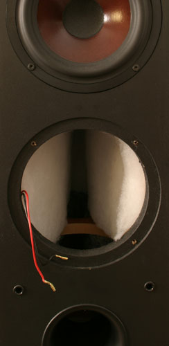
I had some trepidations about recabling, as Dali installs the passive
crossovers in a separate compartment (only mentioned as a feature in the
Euphonias, but apparently used elsewhere in their lineup) and plugs the hole
the driver wiring goes through with hot glue. Upgrading the cabling
involved pulling the existing wiring, extracting the hot glue (an end mill on a right angle Dremel
worked well), and greatly widening Dali's existing hole to accommodate
AWG 2 of MI2 and zip cord (the end mill again). MI2 is not especially
flexible and gets even less so when bulked up, so reinstalling the binding post panel on the back of the
speaker means sliding the internal cables further into the speaker. This, in turn,
makes sealing up the new holes difficult as there's a blind two foot reach from
the woofer openings down to the slab of particle board which blocks off the
crossover compartment. Leaving the holes open adds poorly coupled volume
to the speaker cavity which, while nominally extending the speakers' bass reach,
throws off the porting and risks the establishment of funky resonances. I
decided to go ahead with the project as the added volume was fairly small
compared to the overall speaker volume and, worst case, I could always
reinstall Dali's wiring and plug up the routing holes. But any deleterious
effects seem unnoticeable against the overall improvement.
This page has advanced some workarounds for limitations in off the shelf
audio systems. Some DIY (do it yourself) is likely required to pull out
passive crossovers for active biamping, but the rest can be accomplished just by
buying the right gear and turning the right knobs. If you're also willing
to solder up your own cables you can save a bunch of money. As a parting
remark for the cable DIYer I'll reiterate the point speaker cable inductance kills; splashing out on
cabling doesn't do any good if all that money doesn't drive the
inductance down. As of this writing small quantity list pricing on AWG 12
zip cord was US$ 0.60 per foot, Kimber 8VS was US$ 7.50 per foot, Goertz MI2 US$
10 and MI3 US$ 25 per foot. This means that for less money you can run 10
times more zip cord than 8VS, 15 times more than MI2, and 40 times more than
MI3. Inductances in parallel divide, so the roughly 190 nH/m inductance of zip
cord can easily and cheaply be brought down by doubling, tripling, quadrupling,
or even more upling zip cord (so long as you connect it right). This approach has its limitations—32
sections of zip cord have about the same inductance as MI2 but cost twice as
much, are far bulkier, and considerably harder to handle—but it's the best
way I know to get inductance down short of a planar geometry. For example,
Pear's AWG 12, $7.50 per foot Comice
is basically tripled AWG 16 zip cord (at 7.5 times the price). On cue,
Pear's claimed 60 nH/foot inductance is right around a third of zip cord's.
Surprisingly, Cardas and Kimber don't strand their cables this way. In
particular, 8VS approximates octupled AWG 18 zip and could trivially have its
color coding changed to result in such termination. 8VS's pair spacing is
wider than zip so the resulting inductance is probably around 35 or 40 nH/foot,
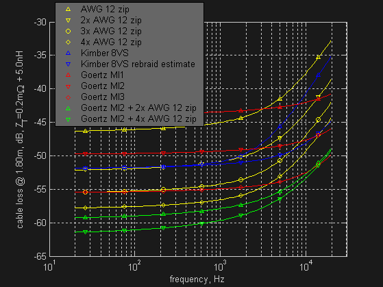
comparable to quintupled instead of octupled zip. As the figure below
shows, such rebraiding offers a dramatic improvement which moves the frequency
at which MI2 outperforms 8VS from 2.4 kHz to 13 kHz. Quadrupled AWG 12 zip
has higher inductance than rebraided 8VS but beats MI2 below 14 kHz or so due to
its lower resistance. The zip's a third the price of 8VS and quarter the
price of MI2 as well as being a good bit easier to terminate than MI2, so quadrupling
it is an attractive proposition. Similarly,
augmenting MI2 by strapping a run or two of zip on each side produces results
comparable to MI3 for under half the list price. MI2 is not terribly hard
to find used while MI3 seldom turns up, so in practice MI2 plus zip cord ends up
being about a quarter the price of MI3.
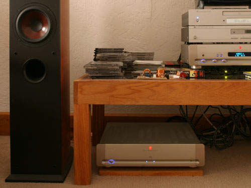 My stereo is a vertical biamp with an active crossover. Hardware details are
- Dali Suite 2.8 floorstanding speakers, passive crossovers removed,
internal wiring upgraded to MI2 + 2x AWG 10 zip, on spikes
- Ashly XR-1001 active crossover, 24dB/octave Linkwitz-Riley
crossovers set to 1.9kHz
- Parasound Halo P3 preamplifier and two Parasound Halo A23 power
amplifiers, XLR interconnect with the Ashly, doubled Goertz MI2 to
the Suite 2.8s, -10 dB power amp gain (previously a NAD C352 used as a preamp and
as an integrated amp before that)
- Cambridge Azur 640C v1 CD player with RCA to XLR
interconnect (previously a NAD C541 and briefly a
refurb Cambridge D500SE which went tits up)
- Cambridge T500 tuner with RCA interconnect
I bought the A23, P3, and MI2 used off Audiogon,
the XR-1001 used from eBay, and the Suite
2.8s new from Speakerlab, while the
640C and T500 came from Spearit as
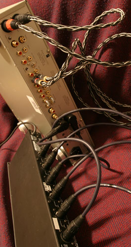
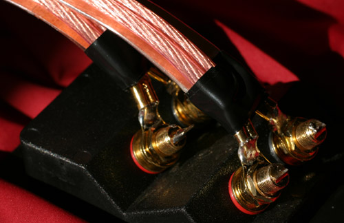
closeouts and refurbs (the table in the photo at right was built by a local high school kid who wanted
to try his hand at furniture; I found it on Craigslist).
The cabling and interconnects are soldered up using parts from PartsExpress or extra
stuff I had lying around. I first bought Kimber 8VS to biwire when I was running a
mono amp and added some Kimber 4VS when I switched to a horizontal biamp. 4VS
is not so great so I added more 8VS. I converted to vertical biamp
a few months later, first shortening the 8VS runs and then switching to MI2. The XLR interconnects between
the XR-1001, P3, and A23s all use PartsExpress' 22 AWG Dayton MSC microphone
cable. Interconnects are using either Neutrik XLRs—often marketed as high
end, but available for a few dollars US even in small quantities—or the equally
low cost, gold plated, Dayton locking
RCAs. Speaker cabling is using Dayton 1/4" spade lugs, 3/8"
ring terminals, or 3/8" rings converted to spades. Gold plated, crimped, and soldered with as little cable breakout
as possible. Total system cost is about the same as the closeout price on a pair
of Dali Helicon 400s. And, speaking from personal experience,
the sound's a sight better than the 400s on a passive vertical biamp.
The incremental upgrades have made for an interesting journey through
the world of sound, starting with a monowired mono amp and progressing through
nearly every step from there up to a heavily modified active vertical
biamp. There have been curious discoveries along the way, ranging from
learning to tap the tips of non-locking banana plugs with a hammer every so
often to keep them tight to how best to solder up two foot long pieces of
disassembled MI2. Some things are just wacky. While I wasn't
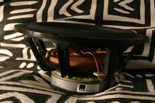
surprised to discover Dali's internal wiring was individual bits of AWG 16, it's remarkable the two tweeter wires run down opposite sides of
the speaker. Building crossovers out of particle board and baling wire and
not putting zip cord in a US$ 1250 speaker is one thing, but installing wiring
to maximize inductance is another (one wonders if the innards of a Helicon or
Euphonia are any better). On the other hand, Parasound graciously emailed
schematics to a friend of mine trying to fix an A23 fried by an over watered
plant. There have been weeks of coding, thinking, cutting, stripping,
crimping, soldering, checking pinouts, making connectivity measurements, and
taking things apart and putting them back together again. I've met a
family in a '57 Chevy at their storage locker, salvaged boards from a friend's
remodel, ended up wishing I'd moved my living room into my dining room to get
better speaker placement, and caught Speakerlab loaning out an amp I
had money down on. But, in the end, what it comes down to is thousands of
hours admiring beautiful music.
legal information
copyright 2005–2009 by Todd West
last modified 2009.09.12